|
Promoting Fairness and Efficiency |
|||
|
|
|
|
|
|
Promoting Fairness and Efficiency |
|||
|
|
|
|
|
|
|
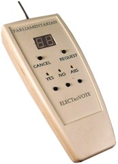
SPEAK and VOTE
COMBO™ SPEAKER REQUEST and VOTE MODULE These 2 1/4" x 5 1/2" modules contain the "Request" and "Cancel" push buttons and the "Digital Displays" showing the Requester's position in the queue. Just below are the three voting choice push buttons "YES", "NO" and "ABS" (abstain) and the green, red and yellow LEDs which indicate the vote choice made.
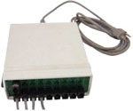
The Power Supply is a 7" x 6" x 2" module with a bank of modular jacks at one end which receive the cable ends from all the Council Member's Vote/Request modules. On the opposite end where the 110 VAC power chord connects are the modular jacks for the cable ends from the Clerk's Vote Control module, the Vote Display Panels, and the Mayor's Request Control.
SPEAKER REQUEST CONTROL Click Here to view information
CLERK’S CONTROL MODULE The Clerk’s
Control Module has three push button switches for turning the system on
and off, for displaying the vote and for resetting the system for a If the "lockout" mode is activated the vote choices made by each Voting Module can be changed only until the vote has been displayed. Thereafter, they cannot. To cancel this mode follow the directions given in the Programming and Operating Instructions. Also, on the back surface is a six conductor modular jack used for the connection to a desktop printer.
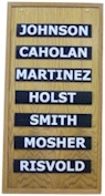
VOTE DISPLAY PANELS The Display Panels are constructed using natural wood with a clear satin finish. Veneers of most any specie desired are available. Oak, Cherry, Walnut, Teak, Birch and Mahogany are standard.
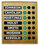
LARGE DISPLAY PANELS The Large Display Panels accommodate nameplates 2" X 12" and have Green, Red and Yellow LED arrays 2" in diameter. These panels are suitable for viewing distances up to 80 feet. Panels are 24" wide, 1 Ľ" thick and of a height as is required by the number of voting members. For 5 members height is 26", 7 members – 29", 9 members – 30", 11 members – 36", 13 members - 42", and 15 members – 48". For systems over 17 members, special panel design will be submitted.
SMALL DISPLAY PANELS The Small Display Panels accommodate nameplates ľ" X 4 ˝" and have 1" diameter LED arrays. These panels are suitable for viewing distance of up to 25 feet. Panels are 10" wide, 1 1/4" thick. Heights are, for 5 members -14", 7 members – 16". 9 members – 18", 11 members – 19", 13 members – 19" and for 15 members 21 1/2'". These Panels are frequently used in situations where it is difficult for the voting members to view the primary Display Panels. SET OF INDIVIDUAL VOTE DISPLAY PANELS These Individual Panels - one for each member - are 4" high by 24" wide by 1 1/4" thick with 2" by 12" name plates. They are intended for placement in front of each individual voting member. CUSTOM DISPLAY PANELS can be price quoted for any situation or design concept, special décor or extra long viewing distances.
DISPLAY PANEL OVERLAYS Display Panel Overlays are available for situations wherein more than one voting body will be using the system. Rather than having to exchange the individual nameplates on the primary Display Panel, a separate name holder portion of a panel is hung in place. If the two voting bodies are not equal in number, the discrepancy is accounted for by employing the "Absentee" feature on the Clerk’s Control Module.
For further information contact: Forespar Products Corporation email: electrovote@forespar.com Phone: (949) 858-8820 |
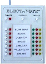 new sequence of voting. Down the left side of the module is a column of
push button switches, one for each voting module, with a red LED
opposite each switch. If a voting member is absent the switch for that
member is pressed and the LED becomes permanently illuminated until
deactivated upon the return of the voting member. In addition to being
an indicator of an absentee, this feature also informs the system’s
microprocessor that a voting sequence may be displayed without a vote
from the absentee position. These red LED’s also illuminate when each
member present votes. Thus, the Clerk need only see a fully lit column
to know to display the vote. Down the right side of the module are
columns of Green, Red and Yellow LED’s, which illuminate to show each
voting member’s choice when the Vote Display button is pressed.
new sequence of voting. Down the left side of the module is a column of
push button switches, one for each voting module, with a red LED
opposite each switch. If a voting member is absent the switch for that
member is pressed and the LED becomes permanently illuminated until
deactivated upon the return of the voting member. In addition to being
an indicator of an absentee, this feature also informs the system’s
microprocessor that a voting sequence may be displayed without a vote
from the absentee position. These red LED’s also illuminate when each
member present votes. Thus, the Clerk need only see a fully lit column
to know to display the vote. Down the right side of the module are
columns of Green, Red and Yellow LED’s, which illuminate to show each
voting member’s choice when the Vote Display button is pressed.